Integrated Models

Integrating Self-Steering to the stern of a boat ensures both a strong and elegant installation, part of the gear remaining hidden inside.

It also allows to lead control lines internally to blocks on boat's steering quadrant, then to jamming cleats in cockpit for instant connect, disconnect or trim.

Additional bonus : when wind is unstable or inexistant, a small tiller pilot located inside the lazarette drives the servo-pendulum which still provides power to move the rudder, feeding on mere milliamps.

Integrating CapeHorn: easier than it looks, even afloat

All necessary fittings provided. 

However, blocks and other hardware needed to lead lines to boat's steering system are not, being different in type on different boats.

A hole saw held perfectly horizontal and parallel to keel cleanly cuts hole for support tube.

Glass laminate (or weld) aft end of tube to hull.

Forward end of mounting tube supported by two struts
(supplied with appropriate fittings) at an angle between 90° and 120°, to reach either underside of deck or pads bonded to hull.

Struts outside on stern platform.

Tube welded to steel hull.

Aluminium tube offered for welding to aluminum hull.

Welding impractical? Delrin collar cut to transom angle, two halves bolted together, both sides of transom. 

Second pair of struts added if mounting tube extends some distance past transom.

Outboard rudder or boarding ladder? CapeHorn off-centre.

Only measurable effect of offset felt if boom extends far aft, close to vane : boat could not sail as close to wind when vane on leeward side, wind received by vane being deflected by leech of sail directly to windward ; other tack, or as soon as sheets are eased, problem disappears.

Reduced paddle area when heeled has no effect because when there is heel, there is most often speed. The force generated by the paddle being proportional to the square of speed through water, the paddle generates much more power than is needed; paddle area is critical only at low speed, which produces little heel.

All struts and braces adjustable. Slip horizontal axle through tube. Fasten quadrant to forward end, wind vane tower aft.

Diagonal braces to deck support tower.

Control lines led through blocks fastened to quadrant or disk or short auxiliary tiller (such as the tiller of a hydraulic system).

To ensure ideal 2:1 ratio between CH quadrant tilt and rudder angle (for 10° tilt, 5° rudder), blocks located from rudder axis at distance equal to CH quadrant radius.

From there, lines are led to jamming cleats in cockpit. For instant connect, disconnect or trim.

Vane connected and adjusted for weather or lee helm by pulling lines tight and cleating them.

Releasing lines instantly disconnects vane for hand steering.

Internal connection impractical?

Control lines turn wheel by going around stops placed on wheel spokes at distance from wheel hub ensuring 2:1 ratio between quadrant tilt and rudder angle.

Teak drum on wooden wheel.

Control lines led through fairleads on tiller located at a distance twice the radius of CH quadrant (2:1 ratio), then forward to jamming cleats.

If quadrant is inside and tiller outside, control lines are led out through holes in sides or back of cockpit.

No room inside lazarette for windvane quadrant ?

A tube extends above horizontal axle, to work as control arm.

On a boat with outboard rudder, gear offset.

Power transmitted to back of rudder head through lines led to blocks on rudder head.

Since there are no lines to it, tiller can be lifted to vertical (or removed) while CapeHorn is steering, leaving cockpit free of obstruction.

Norwegian stern, servo-pendulum connected to back of rudder through rigid control arm.

To allow use of davits on boat with step stern, windvane tower at forward end of horizontal axle passing through the deck.

If your boat presents a specific problem, send us photos showing its stern and steering gear belowdecks. We are not without imagination and may suggest an original solution.

Jean-du-Sud or Spray ?

Jean-du-Sud for boats below 35'-40'

Spray for larger boats

Overall length of yacht is only a rough guide in the choice between the lighterJean-du-Sud or heavier Spray models. The main criterion is in fact the size of its rudder and the amount of effort required to move it.

A 40 ft. plus boat that is well balanced and easily steered, could still use the smaller Jean-du-Sud model (provided its freeboard is not too high). On the other hand, a boat that is not so well balanced and that is hard to steer, would need the larger and more powerful Spray or Joshua, even if it is shorter than 40 ft.

Determining factor in the choice is the rudder dimensions (total area, type, aspect ratio), combined with height of horizontal axis above the waterline. Sail balance should be also taken into account.

Mounting tube (OD):
Stock of steering oar:
Width of paddle:
Paddle length proportional to boat's rudder

JdS  64 mm (2.5"),    Spr  69 mm (3.5")
JdS 25 mm (1"),      Spr 32 mm (1.25")
JdS 128 mm (5"),    Spr 153 mm (6")

How to measure

To custom-build a CapeHorn four dimensions are needed:

1. LMT (Length of Mounting Tube)
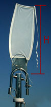
2. HWT (Height of Windvane Tower)
3. HWL (Height of horizontal axle above WaterLine)
4. Average height and width of rudder

1. Length of Mounting Tube (LMT)

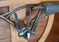
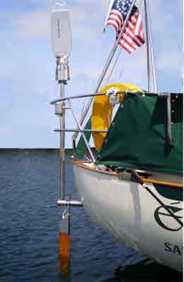
Horizontal axle links outboard steering oar to inboard quadrant pivoting inside tube passing through hull called Mounting Tube. Its length (LMT) is measured between aft face of CapeHorn quadrant to aftermost part of hull or any of its appendages that could be in way of steering oar. Aft end of the mounting tube should also clear trailing edge of rudder if it extends past hull.

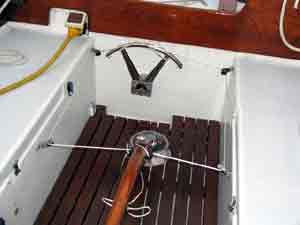
To measure LMT, first determine the optimum position of CapeHorn quadrant in lazarette or cockpit.

Dimensions of Quadrant

Quadrant radius :

  • JdS : 8" (205mm) 1" (25 mm) thick
  • Spray :11" (280 mm ) 1.25" (32 mm) thick

For 360° quadrant movement, circular space (CS) needed at forward end of tube :

  • 16" (410mm) diameter for JdS
  • 22" (560mm) for Spray

If space (inside lazarette or in cockpit) is limited to one half-circle below or above the horizontal axis, gear will work just as well, but possibility of flipping pendulum up for storage along windvane tower is lost.

If only a few inches short, a smaller quadrant is supplied. Performance is not affected and ideal 2 : 1 ratio between quadrant tilt and rudder angle is retained if blocks on steering quadrant (or aux. tiller) are placed at a distance (from rudder axis) equal to CapeHorn quadrant radius. Only load on control lines and blocks is increased.

Quadrant inside lazarette: Ideal position arrived at by taking into account both space required for quadrant itself, and lead of control lines.

Quadrant mounted indifferently above or below horizontal axle.

In many lazarette installations, top of quadrant reaches a few inches below deck and turning blocks can be bolted under it.

Mounting tube through both transom and aft cockpit bulkhead, locates quadrant in cockpit (often under helmsman's seat)...

...ensures both simple and strong installation, both ends of tube supported by a bulkhead.

Leave room for autopilot connected to co-axial control mechanism in front of quadrant since autopilot only controls steering oar, smallest tiller-type unit steers regardless of boat size, feeding on mere milliamps.

If space is limited, autopilot can be located elsewhere and connected to control arm through blocks and light lines (with bungee pulling the other way).

2. Height above Waterline (HWL)

If U-shaped metal plate linking steering oar to its stock is kept above water, drag kept to minimum.

Plate extends below horizontal axle
13" for JdS
19" for Spray
This height is considered a minimum.

Knowing height of horizontal axle above waterline and dimensions of yacht's rudder ensures steering oar provides adequate power to move rudder in all conditions, with minimum drag.

3. Standard Height of Windvane Tower (HWT)

JdS: 53" (135 cm)
Spray: 65" (165 cm)
above horizontal axle

In most cases locates windvane in clean air.


Increased to reach over pilothouse, bimini or arch.

Reduced to duck under mizzen boom.


Arch high enough, vane kept below.

Light air vane extends 24" (60 cm) above top of tower.

Heavy weather vane, 17" (432 mm).